Intrinsic Adjustments - Machined EVA (RS3D)
This page explains all relevant features on the Intrinsic Adjustments page of LaserCAM Prescribe for Machined EVA (RS3D) prescription.
Overview
Navigation
Click Intrinsic Adjustments from the menu to access this page in LaserCAM Prescribe.
Page Layout
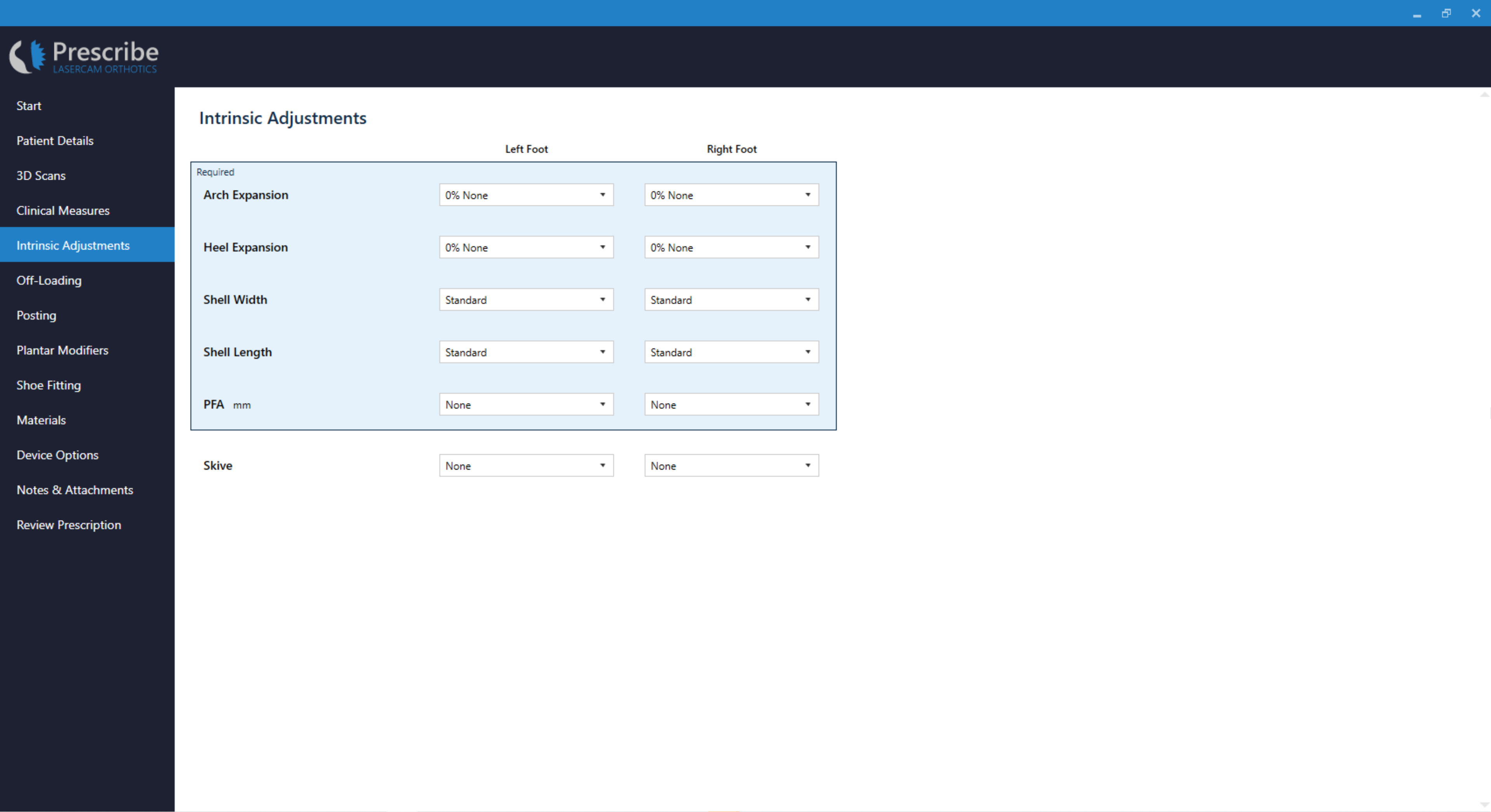
Page Fields
Arch Expansion
Arch Expansion, sometimes referred to as a Arch Fill, is a percentage (%) decrease in the height of the medial longitudinal arch (MLA).
This modification is based on the height of the Medial Arch Ref Point that is placed on the 3D scan during computer-aided design.
| Available Selections | Percentage of Expansion |
|---|---|
| None | 0% |
| Minimal | 10% |
| Standard (Default) | 20% |
| Maximum | 30% |

Clinicians are encouraged to mark the peak MLA location on the foot prior to 3D scan capture. Without marking this location on the scan the peak MLA location is left to the discretion of the individual undertaking the computer-aided design, which is often not the clinician. We highly recommend that you mark all recommended Ref Points prior to 3D scanning.
An orthotic laboratory may change the default percentages (%) for the Arch Expansion. These percentages are listed alongside the text option, e.g. - None (0%). Please be aware that the examples below are based on standard percentages and may not represent your laboratories specific configuration.
None (0%)
The None selection option indicates that the peak height of the MLA will be at the same height as the Medial Arch Ref Point.

Minimal (10%)
The Minimal (10%) selection option indicates that the peak height of the MLA will be 10% lower compared with the Medial Arch Ref Point.
Standard (20%)
The Standard (20%) selection option indicates that the peak height of the MLA will be 20% lower compared with the Medial Arch Ref Point.

Maximum (30%)
The Maximum (30%) selection option indicates that the peak height of the MLA will be 30% lower compared with the Medial Arch Ref Point.
Heel Expansion
Heel Expansion is a percentage (%) increase in the width of the heel from the widest points of the medial and lateral heel.
This modification is based on the width between the Medial Heel Ref Point and the Lateral Heel Ref Point that are placed on the 3D scan during computer-aided design.
| Available Selections | Percentage of Expansion |
|---|---|
| None | 0% |
| Minimal | 5% |
| Standard (Default) | 10% |
| Maximum | 15% |

None (0%)
The None (0%) selection option indicates that the width of the orthosis at the heel will be 0% wider than the width between the Medial Heel Ref Point and the Lateral Heel Ref Point.

Minimal (5%)
The Minimal (5%) selection option indicates that the width of the orthosis at the heel will be 5% wider than the width between the Medial Heel Ref Point and the Lateral Heel Ref Point.
Standard (Default) (10%)
The Standard (10%) selection option indicates that the width of the orthosis at the heel will be 10% wider than the width between the Medial Heel Ref Point and the Lateral Heel Ref Point.
Maximum (15%)
The Maximum (15%) selection option indicates that the width of the orthosis at the heel will be 15% wider than the width between the Medial Heel Ref Point and the Lateral Heel Ref Point.
Shell Width
Shell Width is a selection that determines the width of the forefoot of the Machined EVA (RS3D) orthosis.
This modification is very lab dependent so you should discuss the specific modelling with your laboratory.
Shell Width is only applicable for Machined EVA (RS3D) orthoses that have a 3/4 Length or Sulcus Length selection for Shell Length.
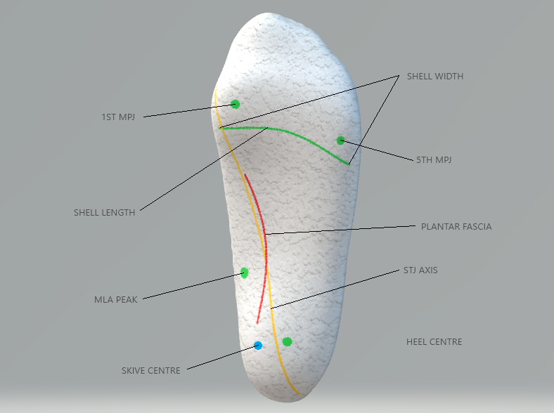
For a precise Shell Width simply mark where you would like the widest portions of the shell to be directly on the foot prior to 3D scanning. This allows the individual undertaking the computer-aided design to reference these marks and provide you with a superior fit.
The image below shows an example of a cast with comprehensive markings. Not all are required, however marking the foot directly is an excellent way to decrease manufacturing error.
| Available Selections | Mediodistal Forefoot Width | Laterodistal Forefoot Width |
|---|---|---|
| Standard (Default) | 5mm wider than 1st MPJ | 10mm wider than 5th MPJ |
| Super Slim | 5mm narrower than 1st MPJ | In-line with 5th MPJ |
| Slim | In-line with 1st MPJ | 5mm wider than 5th MPJ |
| Wide | 10mm wider than 1st MPJ | 15mm wider than 5th MPJ |

Standard (Default)
The Standard selection option indicates that the orthosis will be 5mm wider than the 1st MPJ at the mediodistal forefoot, and 10mm wider than the 5th MPJ at the laterodistal forefoot.

Super Slim
The Super Slim selection option indicates that the orthosis will be 5mm narrower than the 1st MPJ at the mediodistal forefoot, and in-line with the 5th MPJ at the laterodistal forefoot.

Slim
The Slim selection option indicates that the orthosis will be in-line with the 1st MPJ at the mediodistal forefoot, and 5mm wider than the 5th MPJ at the laterodistal forefoot.
Wide
The Wide selection option indicates that the orthosis will be 10mm wider than the 1st MPJ at the mediodistal forefoot, and 15mm wider than the 5th MPJ at the laterodistal forefoot.

Plantar Fascia Accommodation (PFA)
A Plantar Fascia Accommodation (PFA), sometimes referred to as a Plantar Fascia Groove, is an accommodation at a specified depth (mm) in the top surface of the orthosis shaped according to a Curved, Straight or Scan style selection.
It is highly recommended that all prescriptions consider the accommodation of the plantar fascia. Not including an accommodation for the plantar fascia can result in patient discomfort.
The specified depth is measured prior to surface smoothing and is subject to minor variability.
| Default Value | Minimum Value | Maximum Value | Default Selection | Available Selections |
|---|---|---|---|---|
| 0mm | 0mm | 8mm | Curved | Curved |
| Straight | ||||
| Scan |
Curved
| Adjustment Origin | Adjustment Insertion |
|---|---|
| Medial calcaneal tubercle | Inline with 1st metatarsal ~10mm proximal to 1st MPJ |
Straight
| Adjustment Origin | Adjustment Insertion |
|---|---|
| Medial calcaneal tubercle | Inline with 1st metatarsal ~10mm proximal to 1st MPJ |

Scan
A Scan style selection will indicate to technicians that a marking has been made on the plantar fascia prior to 3D scanning, or has been indicated using the Make Drawing tool.
This is the most accurate method of Plantar Fascia Accommodation prescription.
| Adjustment Origin | Adjustment Insertion |
|---|---|
| As per marking | As per marking |
Skive
We recommend that you read the published works of Kevin Kirby to understand relevant theory prior to requesting this adjustment. We have used these works to inform how we recommend the application the Skive adjustment in a computer-aided design environment.
K. Kirby (1989), Rotational equilibrium across the subtalar joint axis, JAPMA
A Skive is an adjustment that is achieved by orientating a flat plane relative to the aligned 3D foot scan during computer-aided design. This plane is orientated in relation to a marked subtalar joint axis, or at a specific angle, and pushed through the 3D foot scan at a specified depth.
| Default Value | Minimum Value | Maximum Value | |
|---|---|---|---|
| Depth | 0mm | 0mm | 10mm |
| Angle (°) | 0° | -90° (lateral skive) | 90° (medial skive) |
There are two methods of prescribing a Skive. Please use the method available to you depending on your 3D scan hardware.
| Prescription Variable | STJ Axis Method (Recommended Method) | Depth/Degree Method |
|---|---|---|
| Angle (°) | Not required | Required |
| Depth (mm) | Required | Required |
| 3D Scan Type | Colour 3D Scan Only | Any 3D Scan |
STJ Axis Method
RECOMMENDED METHOD
This method is only possible when using colour 3D scan formats such as VRML.
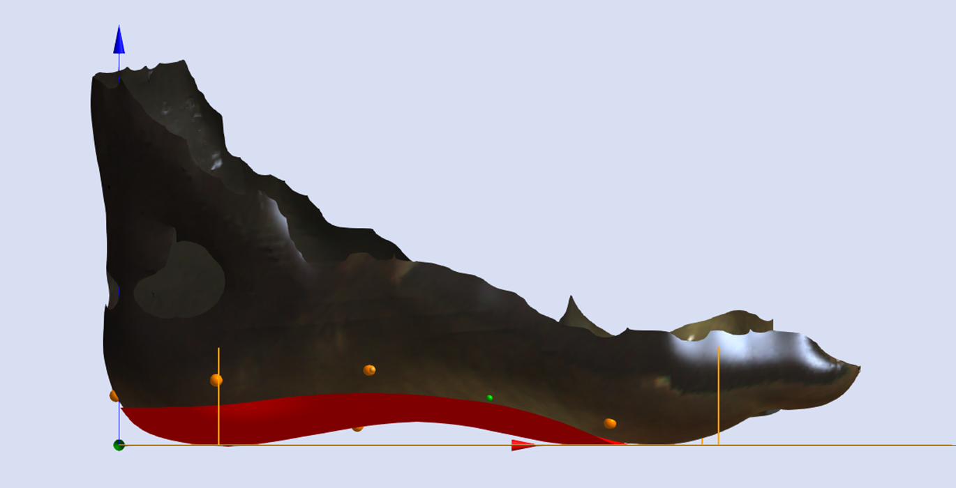
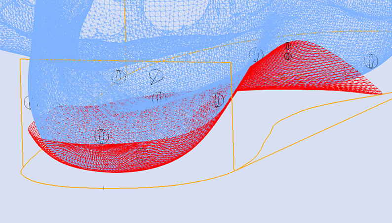
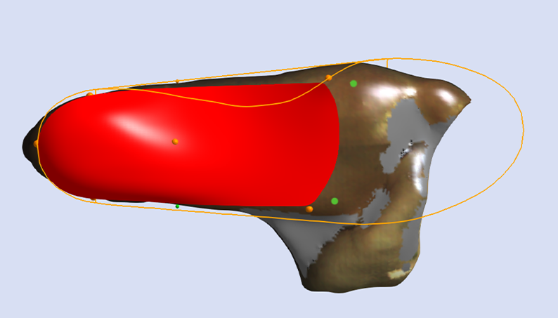
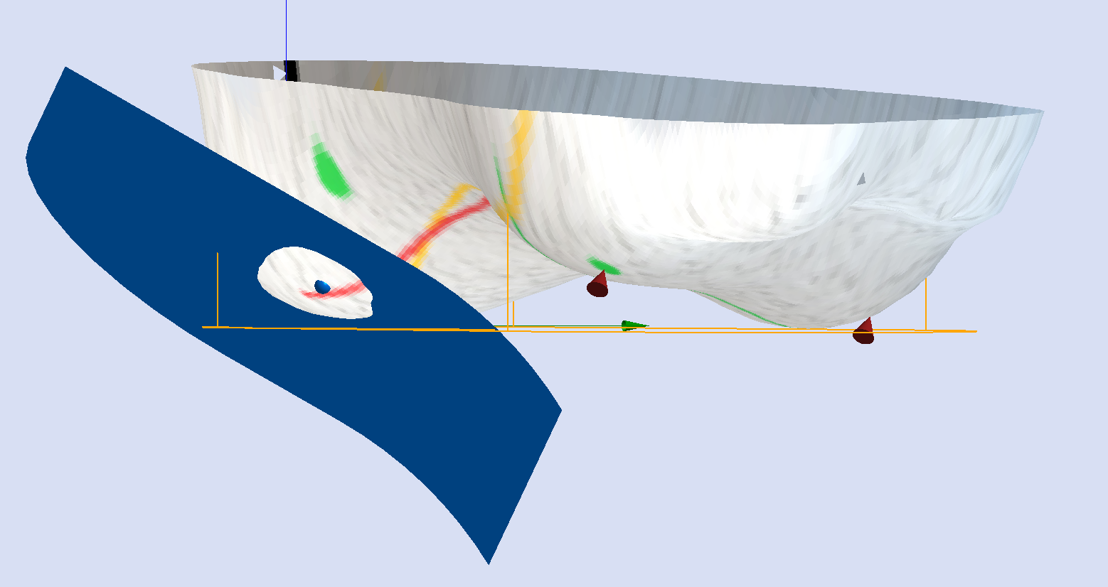
The image below shows the orientation of the adjustment relative to the STJ axis marked on the 3D scan (represented by the yellow line).
Using the STJ Axis Method the only variable required is the Skive Depth.
Skive Angle is not required as the orientation of the skive plane is based upon the marked STJ axis.
Depth/Degree Method
The Depth/Degree Method allows a user to enter a specific Skive Depth and Skive Angle.
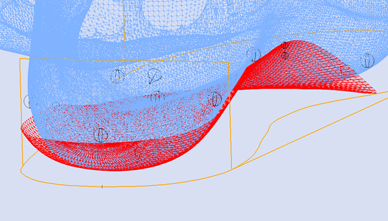
Skive Depth
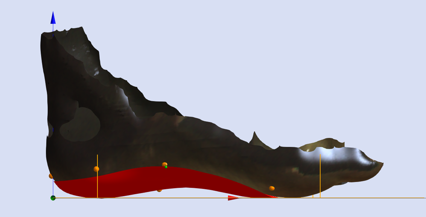
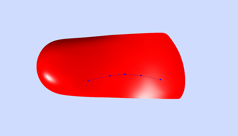
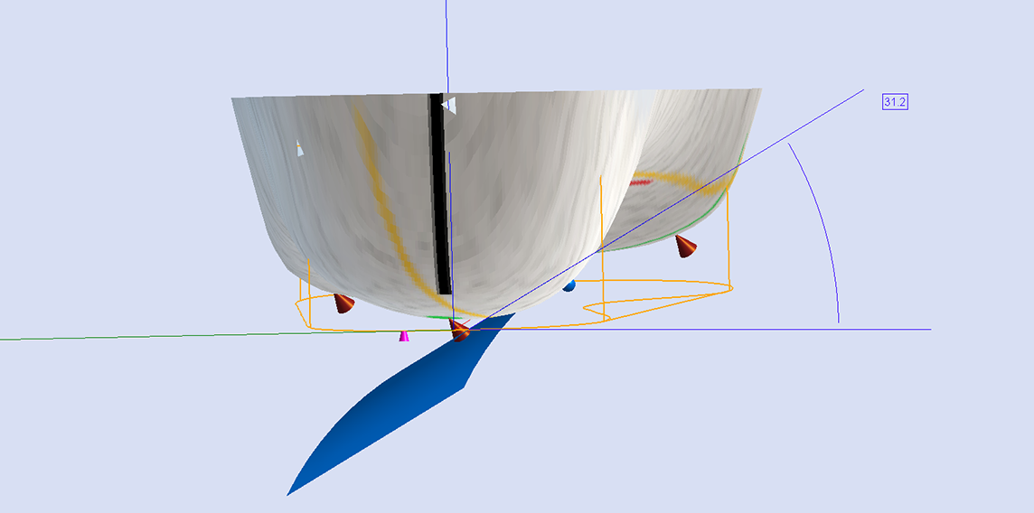
The Skive Depth directly effects the magnitude of supination or pronation moment applied to the subtalar joint. It is measured from the blue depth sphere placed on the 3D foot scan to the skive plane (see image below).
Skive Angle
The Skive Angle defines the frontal plane orientation of the skive plane. If the subtalar join axis is medially deviated then the Skive Angle should increase to ensure a supination moment is being applied to the subtalar joint.
The Skive Angle does not need to be specified when using the STJ Axis Method.
Inclination Angle
The Inclination Angle defines the sagittal plane orientation of the skive plane. The default value is set to Maximum Inclination, which is considered generally appropriate. Specific values may be requested.
| Default Selection | Available Selections |
|---|---|
| Maintain Maximum Inclination | Maintain Maximum Inclination |
| Zero Degree Inclination | |
| Specific Inclination (°) |
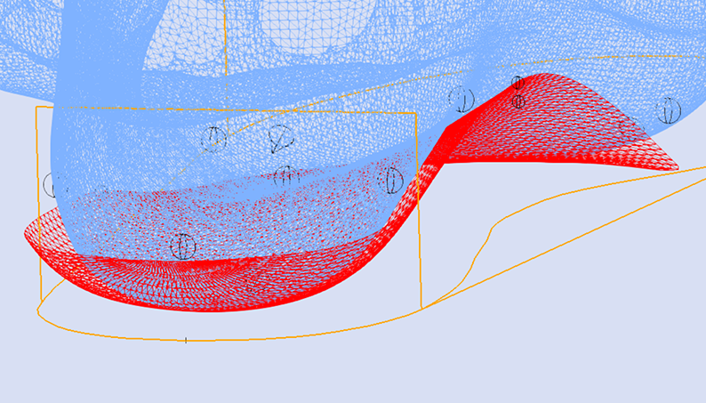
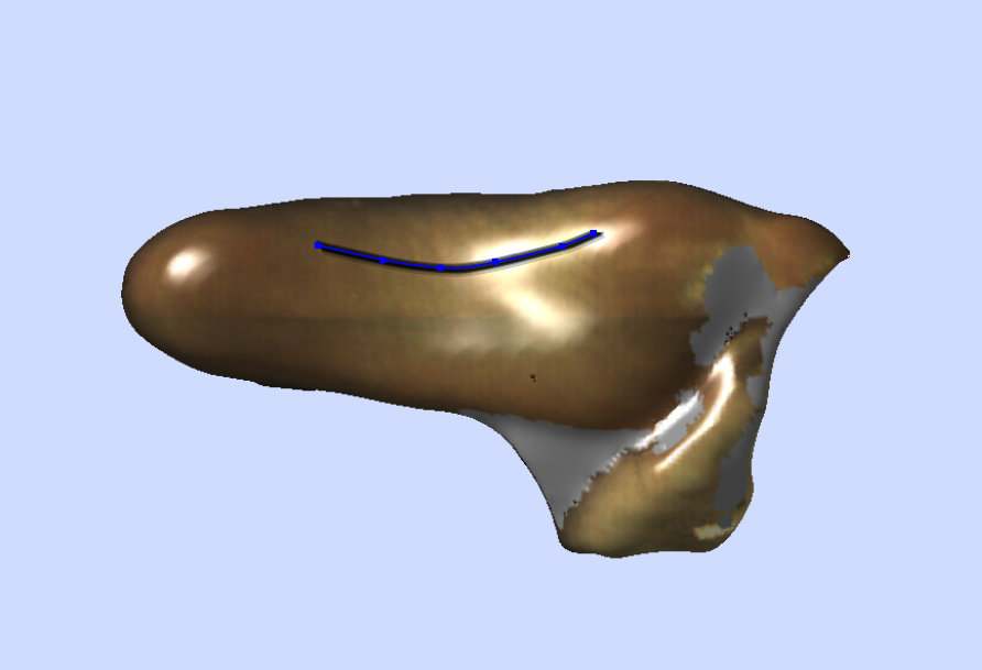
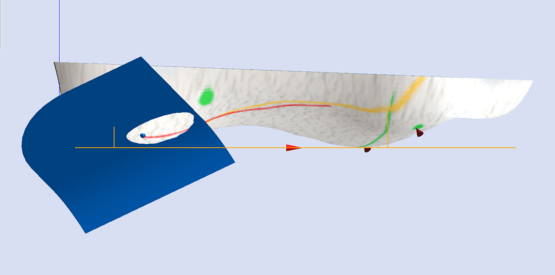
Maintain Maximum Inclination
The image below shows a Skive with the Maximum Inclination of the skive plane.
Additional information regarding Inclination Angle can be found in the following article:
Support
Search Machined EVA (RS3D) Prescription Guide
Related Articles
Submit Support Ticket
If you require further support, please submit a support ticket below.